



'/%3e%3c/svg%3e) 发布
发布 ;}.c{fill:%233f3f3f;}%3c/style%3e%3cclipPath%20id='a'%3e%3crect%20class='a'%20width='24'%20height='24'%20transform='translate(0%20-0.256)'/%3e%3c/clipPath%3e%3c/defs%3e%3cg%20transform='translate(0%200.256)'%3e%3cg%20class='b'%3e%3cpath%20class='c'%20d='M12.938,13.58a.745.745,0,0,1-.328-.076L4.549,9.523a.741.741,0,0,1,0-1.33L12.61,4.212a.74.74,0,0,1,.657,0l8.061,3.981a.741.741,0,0,1,0,1.33L13.267,13.5a.741.741,0,0,1-.329.076M6.553,8.858l6.385,3.153,6.386-3.153L12.938,5.705Z'%20transform='translate(-1.067%20-1.067)'/%3e%3cpath%20class='c'%20d='M12.939,20.964a.729.729,0,0,1-.328-.077l-8.062-3.98a.742.742,0,1,1,.657-1.33l7.733,3.818,7.733-3.818a.742.742,0,1,1,.657,1.33l-8.062,3.98a.729.729,0,0,1-.328.077'%20transform='translate(-1.067%20-3.999)'/%3e%3cpath%20class='c'%20d='M12.939,26.964a.729.729,0,0,1-.328-.077l-8.062-3.98a.742.742,0,1,1,.657-1.33l7.733,3.818,7.733-3.818a.742.742,0,1,1,.657,1.33l-8.062,3.98a.729.729,0,0,1-.328.077'%20transform='translate(-1.067%20-5.547)'/%3e%3c/g%3e%3c/g%3e%3c/svg%3e)
;}.c{fill:%233f3f3f;}%3c/style%3e%3cclipPath%20id='a'%3e%3crect%20class='a'%20width='24'%20height='24'%20transform='translate(0%200.225)'/%3e%3c/clipPath%3e%3c/defs%3e%3cg%20transform='translate(0%20-0.225)'%3e%3cg%20class='b'%3e%3cpath%20class='c'%20d='M21.648,9.056a.754.754,0,0,0-.215-.535l-5.3-5.3a.752.752,0,0,0-.535-.215V3H7.375A2.377,2.377,0,0,0,5,5.376V20.307a2.377,2.377,0,0,0,2.375,2.376h11.9a2.378,2.378,0,0,0,2.376-2.376V9.056ZM16.355,5.584,19.07,8.3H16.923a.569.569,0,0,1-.568-.568Zm2.924,15.584H7.375a.862.862,0,0,1-.861-.861V5.376a.862.862,0,0,1,.861-.861h7.466V7.731a2.084,2.084,0,0,0,2.082,2.082H20.14V20.307a.863.863,0,0,1-.861.861'%20transform='translate(-1.215%20-0.729)'/%3e%3cpath%20class='c'%20d='M10.757,15.514H15.3A.757.757,0,0,0,15.3,14H10.757a.757.757,0,0,0,0,1.514'%20transform='translate(-2.43%20-3.402)'/%3e%3cpath%20class='c'%20d='M18.327,20h-7.57a.757.757,0,0,0,0,1.514h7.57a.757.757,0,0,0,0-1.514'%20transform='translate(-2.43%20-4.86)'/%3e%3c/g%3e%3c/g%3e%3c/svg%3e)

;}.cls-3{fill:%23dbdbdb;}.cls-4{stroke:%23333;stroke-miterlimit:10;stroke-width:0.5px;}%3c/style%3e%3cclipPath%20id='clip-path'%3e%3crect%20class='cls-1'%20width='22'%20height='22'/%3e%3c/clipPath%3e%3c/defs%3e%3cg%20class='cls-2'%3e%3cpath%20class='cls-3'%20d='M16.89,7.8s-1,4.28-4,6a21,21,0,0,1-6.55,1.66,9.87,9.87,0,0,0,6.38,1c3.47-.72,6.82-4.66,6.71-5.43A5.88,5.88,0,0,0,17.6,8.17,2.76,2.76,0,0,0,16.89,7.8Z'/%3e%3cellipse%20class='cls-4'%20cx='11'%20cy='10.94'%20rx='8.53'%20ry='5.49'/%3e%3ccircle%20class='cls-4'%20cx='11'%20cy='10.94'%20r='2.49'/%3e%3c/g%3e%3c/svg%3e)
1.产品概述
HK32F103xCxDxE 系列使用ARM® Cortex®-M3 内核,最高工作频率120 MHz。
HK32F103xCxDxE 内置了大容量存储器:最高512Kbyte Flash、64 KbyteSRAM。此外,可通过FSMC 模块外挂最多1 Gbyte 容量的NOR/PSRAM/NAND/PC Card 存储器,其中有256 Mbyte 的空间可以存放指令,并且可以被片内1 Kbyte 指令Cache 缓存。
HK32F103xCxDxE 内置的CRC 模块提供了数据完整性的检查能力。
HK32F103xCxDxE 内置了丰富的通信接口满足多种通信应用场景:5 路USART/UART、3 路SPI(SPI2/3支持I2S 协议)、1 路SDIO、2 路I2C、1 路CAN 2.0 A/B 和1 路FS USB。
HK32F103xCxDxE 内置2 个高级16 位PWM 计时器(共8 路PWM 输出,其中6 路带死区互补输出),4 个通用16 位PWM 计时器(共16 路PWM 输出),2 个16 位的基本定时器。
HK32F103xCxDxE 提供独立的VBAT 电池电源域,当VDD 主电源掉电时,RTC 模块可在VBAT 供电下继续工作;另外,VBAT 电池电源域提供了84 Byte 的备份寄存器。
HK32F103xCxDxE 内置了丰富的模拟电路:3 个12 位ADC(支持最多16 路外部模拟输入通道同时使用,其中2 路弱驱动信号输入通道和1 路5V 高压信号输入通道)、2 个12 位DAC、1 个温度传感器、1个0.8V 内部参考电压源、1 个可编程电压检测器(PVD)、1 个上电/下电复位(POR/PDR)电路和1 个VBAT电源电阻分压器(分压器输出在片内与ADC 相连)。
HK32F103xCxDxE 支持丰富的功耗模式;在最低功耗模式下,芯片的典型漏电电流小于 100nA。 HK32F103xCxDxE 工作于-40°C 至+105°C 的温度范围,供电电压2.0V 至3 .6V,可满足绝大部分应用环境条件的要求。
完整的HK32F103xC、HK32F103xD 和HK32F103xE 系列产品包括从64 脚至100 脚的两种不同封装。根据不同的封装形式,器件中的外设配置有差异。
由于拥有丰富的外设配置,HK32F103xCxDxE MCU 可适用于多种应用场景:
• 工业应用,如可编程控制器、打印机、扫描仪等
• HMI 人机音视频多媒体交互
• 图形显示设备,如广告显示
• 语音识别设备
• 安全监控设备
• 电机驱动和调速控制
• 物联网低功耗传感器终端,如运动手环等
• 无人机飞控、云台控制
• 玩具产品
• 家用电器
• 智能机器人
• 智能手表
2.产品特性
• ARM® Cortex®-M3 内核
◦ 最高时钟频率:120 MHz
◦ 24 位System Tick 定时器
◦ 支持CPU Event 信号输入至MCU 引脚,实现与板级其它Soc CPU 的联动。
• 工作电压范围
◦ 双电源域:
- 主电源VDD 为2.0 V ~ 3.6 V
- 备份电源VBAT 为1.8 V ~ 3.6 V
◦ 当主电源掉电时,RTC 可继续工作在VBAT 电源下。
◦ VBAT 电源域提供84 byte 备份寄存器。
• 工作温度范围:-40°C ~ +105°C
• VDD 典型工作电流
◦ 运行(Run)模式:19.3 mA@120MHz@3 .3V
◦ 睡眠(Sleep)模式:5.6mA@120MHz@3 .3V(唤醒时间:1 个机器时钟周期)
◦ 停机(Stop)模式
- LDO 低功耗模式:89.4 μA@3 .3V(唤醒时间:10µs)
- LDO 全速工作模式:303 μA@3 .3V
◦ 待机(Standby)模式:3.3 μA@3 .3V(唤醒时间:150µs)
• VBAT 典型工作电流(VDD 掉电)
◦ VBAT RTC 开启模式:2.6 μA@3 .3V
◦ VBAT RTC 关闭模式:2.1 μA@3 .3V
• 存储器
◦ 最高512 Kbyte 的Flash 存储器
- 当CPU 主频不高于24 MHz 时,支持0 等待总线周期。
- 具有代码安全保护功能,可分别设置读保护和写保护。
◦ 64Kbyte 片内SRAM
◦ FSMC 模块可外挂1 Gbyte NOR/PSRAM/NAND/PC Card 存储器(其中,256 Mbyte 的空间可以存放指令,可用于片内Cache 缓存)
• 数据安全
◦ CRC32 校验硬件单元
• 时钟
◦ 外部高速时钟(HSE):支持4 ~ 32 MHz,典型8 MHz
◦ 外部低速时钟(LSE):32.768 kHz
◦ 片内高速时钟(HSI):8 MHz/28 MHz/56 MHz 可配置
◦ 片内低速时钟(LSI):40 kHz
◦ PLL 输出时钟:120MHz(最大值)
◦ GPIO 外部输入时钟:1 ~ 64 MHz
• 复位
◦ 外部管脚复位
◦ 电源复位(POR/PDR)
◦ 软件复位
◦ 看门狗(IWDG和WWDG)复位
◦ 低功耗管理复位
• 可编程电压检测器(PVD)
◦ 8 级检测电压门限可调
◦ 上升沿和下降沿检测可配置
• 通用输入输出端口(GPIO)
◦ 64 脚封装提供51 个GPIO 引脚,100 脚封装提供80 个GPIO 引脚
◦ 所有GPIO 引脚可配置为外部中断输入
◦ 内置可开关的上、下拉电阻
◦ 支持开漏(Open-Drain)输出
◦ 支持施密特(Schmitt)迟滞输入
◦ 输出驱动能力超高、高、中、低四档可选
• 数据通讯接口
◦ 5 路USART/UART(USART1/2/3,UART4/5)
◦ 3 路SPI(SPI2/3 支持I2S 协议)
◦ 2 路I2C
◦ 1 路SDIO
◦ 1 路CAN 2.0 A/2.0B
◦ 1 路全速USB2.0
• 定时器及PWM 发生器
◦ 高级定时器:TIM1/TIM8(带死区互补PWM 输出)
◦ 通用定时器:TIM2/TIM3/TIM4/TIM5
◦ 基本定时器:TIM6/TIM7(支持CPU 中断、DMA 请求和DAC 转换触发)
• 片内模拟电路
◦ 3 个12 位1 MSPS ADC(支持最多16 路外部模拟输入通道同时使用);支持双ADC 模式,采样率最高2 MSPS。
◦ 2 个12 位DAC
◦ 1 个温度传感器
◦ 1 个0.8 V 内部参考电压源
◦ 1 个VBAT 电源电阻分压器(分压器输出在片内与ADC 相连,实现VBAT 电源电压监控)
• DMA 控制器
◦ 2 个独立DMA:DMA1 和DMA2
◦ DMA1 提供7 路通道
◦ DMA2 提供5 路通道
◦ 支持Timer、ADC、SPI、I2C、USART、UART 等多种外设触发
• CPU 调试及跟踪接口
◦ SW-DP 两线调试端口
◦ JTAG 五线调试端口
◦ ARM DWT、FPB、ITM、TPIU 调试追踪模块
◦ 单线异步跟踪数据输出接口(TRACESWO)
◦ 四线同步跟踪数据输出接口(TRACEDO[3:0]、TRACECKO)
◦ 自定义DBGMCU 调试控制器(低功耗模式仿真控制、调试外设时钟控制、调试及跟踪接口分配)
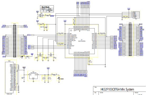
3. 硬件原理图
4. 测评内容
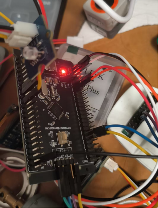
本次测评完成光照度转换成模拟信号检测并通过UART发送主机以波形显示,使用PA1引脚作为ADC模拟信号引脚,使用PA9和PA10作为UART串口引脚 /*USART1:PA9(TX)---PA10(RX)*/,接线如图:
5. 软件代码
代码主要分为2个模块,一部分完成uart输出数据,一部分完成ADC检测光照度(注意使用了DMA传输转换结果):
/*******************************************************************************
* @copyright: Shenzhen Hangshun Chip Technology R&D Co., Ltd
* @filename: main.c
* @brief: Main program body
* @author: AE Team
* @version: V1.0.0/2023-11-09
* 1.Initial Version
* @log:
*******************************************************************************/
/* Includes ------------------------------------------------------------------*/
#include "main.h"
#include "hk32f103xxxxa_eval.h"
/** @addtogroup HK32F103xxxxA_StdPeriph_Examples
* @{
*/
/** @addtogroup ADC_DMA
* @{
*/
/* Private typedef -----------------------------------------------------------*/
/* Private define ------------------------------------------------------------*/
#define ADC1_DR_Address ((uint32_t)0x4001244C)
/* Init Structure definition */
static RCC_ClocksTypeDef RCC_Clocks;
static __IO uint32_t TimingDelay = 0;
static ADC_InitTypeDef ADC_InitStructure;
static DMA_InitTypeDef DMA_InitStructure;
__IO uint16_t ADCConvertedValue;
/* Private macro -------------------------------------------------------------*/
/* Private variables ---------------------------------------------------------*/
/* Private function prototypes -----------------------------------------------*/
static void Delay(__IO uint32_t nTime);
static void RCC_Configuration(void);
static void GPIO_Configuration(void);
static void USART_Config(void);
/* Private functions ---------------------------------------------------------*/
/**
* @brief Main program.
* @param None
* @retval None
*/
int main(void)
{
/*!< At this stage the microcontroller clock setting is already configured,
this is done through SystemInit() function which is called from startup
file (startup_hk32f103xxxxa.s) before to branch to application main.
To reconfigure the default setting of SystemInit() function, refer to
system_hk32f103xxxxa.c file
*/
/* SysTick end of count event each 10ms */
RCC_GetClocksFreq(&RCC_Clocks);
SysTick_Config(RCC_Clocks.HCLK_Frequency / 100);
USART_Config();
/* System clocks configuration ---------------------------------------------*/
RCC_Configuration();
/* GPIO configuration ------------------------------------------------------*/
GPIO_Configuration();
/* DMA1 channel1 configuration ----------------------------------------------*/
DMA_DeInit(DMA1_Channel1);
DMA_InitStructure.DMA_PeripheralBaseAddr = ADC1_DR_Address;
DMA_InitStructure.DMA_MemoryBaseAddr = (uint32_t)&ADCConvertedValue;
DMA_InitStructure.DMA_DIR = DMA_DIR_PeripheralSRC;
DMA_InitStructure.DMA_BufferSize = 1;
DMA_InitStructure.DMA_PeripheralInc = DMA_PeripheralInc_Disable;
DMA_InitStructure.DMA_MemoryInc = DMA_MemoryInc_Disable;
DMA_InitStructure.DMA_PeripheralDataSize = DMA_PeripheralDataSize_HalfWord;
DMA_InitStructure.DMA_MemoryDataSize = DMA_MemoryDataSize_HalfWord;
DMA_InitStructure.DMA_Mode = DMA_Mode_Circular;
DMA_InitStructure.DMA_Priority = DMA_Priority_High;
DMA_InitStructure.DMA_M2M = DMA_M2M_Disable;
DMA_Init(DMA1_Channel1, &DMA_InitStructure);
/* Enable DMA1 channel1 */
DMA_Cmd(DMA1_Channel1, ENABLE);
/* ADC1 configuration ------------------------------------------------------*/
ADC_InitStructure.ADC_Mode = ADC_Mode_Independent;
ADC_InitStructure.ADC_ScanConvMode = ENABLE;
ADC_InitStructure.ADC_ContinuousConvMode = ENABLE;
ADC_InitStructure.ADC_ExternalTrigConv = ADC_ExternalTrigConv_None;
ADC_InitStructure.ADC_DataAlign = ADC_DataAlign_Right;
ADC_InitStructure.ADC_NbrOfChannel = 1;
ADC_Init(ADC1, &ADC_InitStructure);
/* ADC1 regular channel10 configuration */
ADC_RegularChannelConfig(ADC1, ADC_Channel_1, 1, ADC_SampleTime_55Cycles5);
/* Enable ADC1 DMA */
ADC_DMACmd(ADC1, ENABLE);
/* Enable ADC1 */
ADC_Cmd(ADC1, ENABLE);
/* Enable ADC1 reset calibration register */
ADC_ResetCalibration(ADC1);
/* Check the end of ADC1 reset calibration register */
while (ADC_GetResetCalibrationStatus(ADC1))
{
}
/* Start ADC1 calibration */
ADC_StartCalibration(ADC1);
/* Check the end of ADC1 calibration */
while (ADC_GetCalibrationStatus(ADC1))
{
}
/* Start ADC1 Software Conversion */
ADC_SoftwareStartConvCmd(ADC1, ENABLE);
while (1)
{
// Delay(50);
// printf("ADC Channel10 Data is 0x%04X\r\n",ADCConvertedValue);
printf("%d,\n",ADCConvertedValue);
}
}
/**
* @brief Configures the different system clocks.
* @param None
* @retval None
*/
void RCC_Configuration(void)
{
/* ADCCLK = PCLK2/4 */
RCC_ADC1CLKConfig(RCC_PCLK2_Div4);
/* Enable peripheral clocks ------------------------------------------------*/
/* Enable DMA1 clock */
RCC_AHBPeriphClockCmd(RCC_AHBPeriph_DMA1, ENABLE);
/* Enable ADC1 and GPIOC clock */
RCC_APB2PeriphClockCmd(RCC_APB2Periph_ADC1 | RCC_APB2Periph_GPIOA, ENABLE);
}
/**
* @brief Configures the different GPIO ports.
* @param None
* @retval None
*/
void GPIO_Configuration(void)
{
GPIO_InitTypeDef GPIO_InitStructure;
/* Configure PC.00 (ADC Channel10) as analog input -------------------------*/
GPIO_InitStructure.GPIO_Pin = GPIO_Pin_1;
GPIO_InitStructure.GPIO_Mode = GPIO_Mode_AIN;
GPIO_Init(GPIOA, &GPIO_InitStructure);
}
/**
* @brief Configure the USART Device
* @param None
* @retval None
*/
static void USART_Config(void)
{
USART_InitTypeDef USART_InitStructure;
/* USARTx configured as follow:
- BaudRate = 115200 baud
- Word Length = 8 Bits
- Stop Bit = 1 Stop Bit
- Parity = No Parity
- Hardware flow control disabled (RTS and CTS signals)
- Receive and transmit enabled
*/
USART_InitStructure.USART_BaudRate = 115200;
USART_InitStructure.USART_WordLength = USART_WordLength_8b;
USART_InitStructure.USART_StopBits = USART_StopBits_1;
USART_InitStructure.USART_Parity = USART_Parity_No;
USART_InitStructure.USART_HardwareFlowControl = USART_HardwareFlowControl_None;
USART_InitStructure.USART_Mode = USART_Mode_Rx | USART_Mode_Tx;
HK_EVAL_COMInit(COM1, &USART_InitStructure);
}
/**
* @brief Redirect the c library function printf to the EVAL_COM1.
* @param None
* @retval None
*/
PUTCHAR_PROTOTYPE
{
/* Send a byte of data to the EVAL_COM1 */
USART_SendData(EVAL_COM1, (uint8_t) ch);
/* Wait for transmit completed */
while (USART_GetFlagStatus(EVAL_COM1, USART_FLAG_TXE) == RESET)
{
}
return (ch);
}
/**
* @brief Set a precise delay with systick timer.
* @param None
* @retval None
*/
static void Delay(__IO uint32_t nTime)
{
TimingDelay = nTime;
while (TimingDelay != 0)
{
}
}
/**
* @brief Called by SysTick_Handler() periodically.
* @param None
* @retval None
*/
void TimingDelay_Decrement(void)
{
if (TimingDelay != 0x00)
{
TimingDelay--;
}
}
#ifdef USE_FULL_ASSERT
/**
* @brief Reports the name of the source file and the source line number
* where the assert_param error has occurred.
* @param file: pointer to the source file name
* @param line: assert_param error line source number
* @retval None
*/
void assert_failed(uint8_t* file, uint32_t line)
{
/* User can add his own implementation to report the file name and line number,
ex: printf("Wrong parameters value: file %s on line %d\r\n", file, line) */
/* Infinite loop */
while (1)
{
}
}
#endif
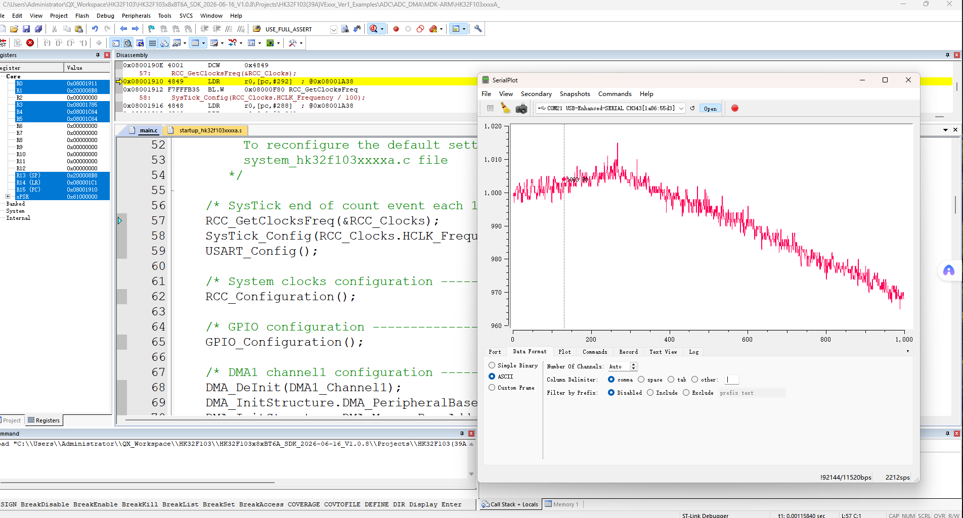
特别注意这一条语句:printf("%d,\n",ADCConvertedValue);这是serial plot要求的格式,同时还要在数据格式端设置接受数据格式,下图是软件设置图与串口传输数据波形图:
;}.c{fill:%23555;}%3c/style%3e%3cclipPath%20id='a'%3e%3crect%20class='a'%20width='18'%20height='18'%20transform='translate(1543%202144)'/%3e%3c/clipPath%3e%3c/defs%3e%3cg%20class='b'%20transform='translate(-1543%20-2144)'%3e%3cpath%20class='c'%20d='M182.144,108.918a.7.7,0,1,1-1.407,0V98.083l-.033.027-.054.05-5.045,5.045a.7.7,0,0,1-1.041-.945l.046-.05,5.045-5.045a2.508,2.508,0,0,1,3.477-.031l.075.072,4.988,5.022a.7.7,0,0,1-.949,1.038l-.05-.046L182.21,98.2l-.066-.061Zm5.394-15.827a.7.7,0,1,1,0,1.407h-12.2a.7.7,0,1,1,0-1.407Z'%20transform='translate(1370.601%202051.909)'/%3e%3c/g%3e%3c/svg%3e "回到顶部")